 |
| July 25, 2012 | Volume 08 Issue 28 |
Designfax weekly eMagazine

Archives
Partners
Manufacturing Center
Product Spotlight
Modern Applications News
Metalworking Ideas For
Today's Job Shops
Tooling and Production
Strategies for large
metalworking plants
Unusual motion projects: Robotic dolphin for the movies
By Don Labriola P.E., QuickSilver Controls, Inc.

Ever wonder how motion control is developed for movie animatronics? Well QuickSilver Controls can tell you a thing a two. The Corvina, CA, company was contacted a while back by KNB EFX Group for motion control help on a fast-turn project: developing the motion control system for a robotic dolphin. The project was for the "Dolphin Tale" movie released in 2011 about Winter, a dolphin that was injured in crab nets and was helped to survive by means of a prosthetic tail (http://www.seewinter.com/).
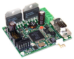
Fourteen of the special actuators in the animatronic dolphin used in some movie scenes were driven by QuickSilver's QCI-D2-MG-01 motion controller, a 2-in. (53-mm) x 2.5-in. (63-mm) closed-loop step motor controller. It provides 12-VDC to 48-VDC and up to 3.5 A continuous and 4.5 A peak. The controller was packaged in a custom, water-sealed container filled with environmentally safe vegetable oil for operation in the dolphin tank.
The size 23 step motors were connected to a number of linear actuators that flexed the dolphin body and tail up or down and side to side. QuickSilver Controls developed a custom software algorithm needed to control the various actuators in smooth, coordinated control from multiple radio-controlled (RC) controllers typically used by movie-making puppeteers. Quick response times helped meet the tight schedule of the project, which was designed by Eric Fiedler of Renegade Designers, Inc., and K&B Effects Group.
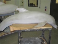
About the robo dolphin
The robotic dolphin was needed as a stand-in for Winter in sequences that would either be too dangerous or difficult, or that could exhaust the real, recovering dolphin. KNB needed to mimic the size, coloration, and water retention of the real dolphin in addition to mimicking its fluid motions. Because the movie needed shots both in the water and at the surface of the water, a full-scale dolphin robot with internal electronics and actuators was used. This eliminated the strings often used with puppets, which would be harder to process out due to their effect on the water surface.
The robotic dolphin needed to operate in salt water up to a depth of approximately 10 m. Its build needed to avoid chemicals that could pollute the aquarium tank or hurt either the real dolphin or the actors in the water. Multiple coordinated actuators were needed to handle the many elements required to model the motions of an actual dolphin. The motions needed to be able to be adjusted live, on the fly, to interact with the actors during the shoot. The preferred method in the movie industry is for the "puppet masters" to control the motions via multiple, sophisticated RC multi-axis control heads. Preprogrammed motions are avoided to prevent downtime for programming between shots. Because the dolphin needed to operate under salt water, the normal radio link was substituted with a small wire that carried the multiplexed signals.
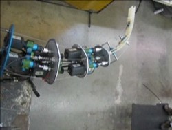
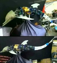
The mechanical spine and muscles of the dolphin were created using several aluminum disks linked together using sets of pivots along the center line, with pairs of waterproof linear actuators providing the ability to flex up and down (axis working together) and side to side (actuators working differentially). The linear actuators were specialty products from Ultra Motion LLC that were driven by low-voltage stepper motors for safety reasons in a conductive saltwater environment. Absolute position feedback was provided by internal, sealed potentiometers. The electronics were made waterproof by mounting the circuit boards into custom sealed cases that were filled with vegetable oil, with a small amount of dried rice added as a desiccant. The food-grade products were used instead of the normal mineral oil and silica gel to prevent any chance of polluting the aquarium tank with harmful chemicals if a leak occurred.
QuickSilver Controls' QCI-D2-MG-01 motion controllers were used to close the loop around the open-loop steppers using the potentiometer. The preferred method would have been to include motor shaft feedback to allow the motor to be commutated for higher performance, but the lead time of the specialty underwater actuators prevented that level of customization. Instead, the motor velocity was commanded using a simple control loop comparing the potentiometer feedback to the commanded signal. The gains were tuned down to smooth out the motions from the RC controller, which only updates about 30 times per second. A secondary processing thread on the controller was used to monitor for, and recover from, jams in the open-loop step motor.
The initial interface between the RC control signals and the controller had been done using small linear potentiometers mechanically connected to standard RC servo actuators. These added complexity and fragility to a system that needed to operate under water. In order to meet the filming schedule, QuickSilver added the ability to use standard RC 1- to 2-msec control pulses (more below.) as a standard option. This capability was added in less than one day, allowing the pulse width signal from the receiver to directly control the motion.
About radio-control (RC) standard pulse width signals
Radio-control planes and cars use a multiplexed pulse width signal scheme to control many axes of control over a single radio link. The various joy sticks, trims, potentiometers, and switches are measured by the processor in the RC control module and can be mixed, processed, and slew and range limited, producing multiple coupled position control signals.
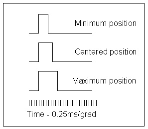
The individual signals are encoded using pulse width modulation. The standard RC controllers and motors nominally use a 1- to 2-msec pulse width, 0 V to 3.3 V, to indicate the desired position, although some can use the extended 0.7- to 2.3-msec timing. For the nominal timing, a 1-msec pulse indicates extreme motion position in one direction, a 1.5-msec pulse represents centered, and a 2-msec pulse indicates the opposite, extreme position. Each of the multiple axes controlled by the RC is provided with its own pulse width modulated (PWM) control signal. The signals are sent in order by the controller and demultiplexed by the receiver. Multiplexing multiple signals lowers the update rate for any particular channel to some 20 to 30 msec.
Source: QuickSilver Controls
Learn more at www.QuickSilverControls.com
Published July 2012
Rate this article
View our terms of use and privacy policy